Numerical Modelling of Underwater Excavation Process
Ir. Xiuhan Chen
Introduction
Both in dredging and deep sea mining engineering, the underwater excavation process is one of the key processes which can give dominant influence on the equipment design and production rate. Therefore it becomes necessary to get a thorough understanding of the physics and build up a numerical model of this process. It is the influence of seawater distinguishes the underwater excavation from the on-land excavation. The influence consists of three issues:
- the confining pressure which equals to the hydrostatic pressure;
- the fluid flow in the cutting area;
- the pore pressure inside the pores of the seabed.
Fig. 1 shows the rock failures under different confining pressures.
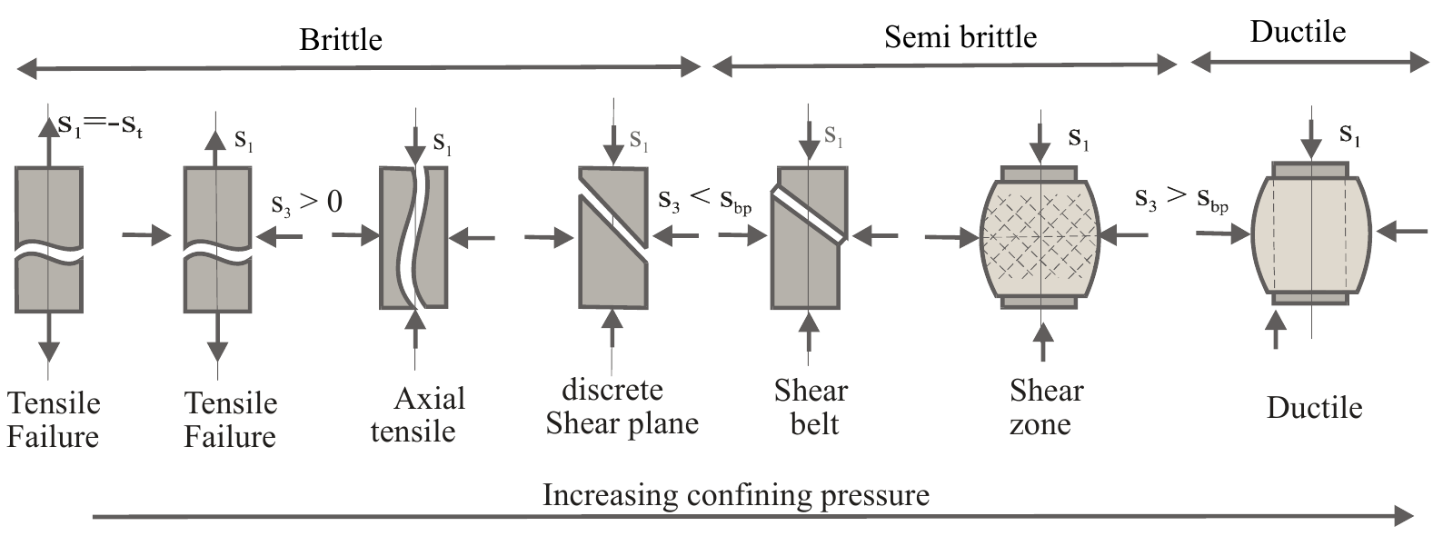
Figure 1: Rock failures under increasing confining pressures
Methodology
Seabed materials could be sand, clay, rock or their mixture. Sand particles are bond-free particles of crystalline shape. The shape of a sand particle determines its ability of rotating instead of shearing. On the other hand, clay grains are glued by recoverable cohesion and adhesion forces, which make this type of material sticky. However, Rock grains are glued by unrecoverable bonding force. According to their mechanical properties, discrete element modeling (DEM) is considered to be the best numerical tool to describe their characteristics and behavior.
On the other hand, finite volume method (FVM) is applied to calculate the fluid pressure and velocity fields when solid structure is changing. The governing equations for the fluid are
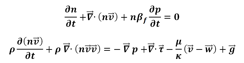
Where t is the time [s], n is the porosity, βf is the compressibility of the fluid [m /N ], p is the fluid pressure [pa], v is the fluid velocity [m/s] and w is the solid velocity [m/s], ρ is the fluid density [kg/m3], τ is the viscous shear stress tensor [N/m2], μ is the dynamic viscosity of the fluid [kg/(m·s)], κ is the permeability of the solid structure [m2].
Design of Sand Particle Geometry
Particle Type 1: A spherical particle.
Particle Type 2: A non-spherical particle made by two partially merged spheres. These two spheres are identical to each other. The distance between the two centers of the spheres equals to the radius of each sphere.
Particle Type 3: A non-spherical particle made by three combined spheres. These three spheres are identical to each other and partially overlapped. The internal structure of this particle is a regular triangle. On each vertex there located a sphere whose radius equals to the side length of the regular triangle.
Particle Type 4: A non-spherical particle made by a combination of four identical spheres. The internal structure of this geometry is a regular tetrahedron, where each vertex is the center of a sphere. The radius of the sphere equals to the side length of this regular tetrahedron.
Particle Type 5: A non-spherical particle made by five identical spheres. The basic structure is two identical regular tetrahedrons with shared bottom face. So in total there are five vertexes and on each vertex there is a sphere located. The sphere’s radius equals to the side length of the regular tetrahedron.
Particle Type 6: A non-spherical particle generated from six identical spheres. The internal structure is two identical square pyramidal pentahedrons who share their square bottom face with each other. All the side lengths in the structure are the same to each other. In total there are six vertexes, and on each vertex there is a sphere center located. The sphere’s radius equals to side length of the pentahedron.
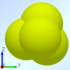
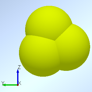
Fig. 2. Geometry design for sand particles
The three moments of inertia (X, Y and Z direction) of type 4 are all identical, which means that particle type 4 is mechanically isotropic. After a series of tests, type 4, the particle made by four combined spheres, is the best particle shape to imitate the natural sand particle, and particle type 5 which is created by a combination of five spheres is the second best design.
Clay-like Materials
Clay-like material has been generated and excavated in both dry and underwater conditions. The sample is an assembly of 200,000 DEM particles, the radii of the particles follows Gaussian distribution where d50 = 0.4mm. the size of the soil sample is 110mm x 11.8mm x 10.2mm and the size of the blade is 12.8mm x 11.6mm x 0.2mm with a cutting angle of 51.5o.
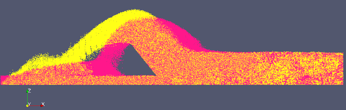
Figure 3: Snapshots captured in both dry and underwater cutting simulations
In Fig. 3, the red part represents the dry cutting while the yellow part represents the underwater cutting. It is observed that in dry cutting the shear layer in front of the blade has a bigger width and its profile is smoother, approaching the nature angle of repose. By contrast, the shear layer in underwater condition is higher and thinner, the slope to the soil bed is much steeper. Besides, settling velocities of particles behind the blade are significantly damped by the surrounding water, so the tail of the cut material can reach a further distance in the underwater condition than in the dry condition.
Conclusion & Recommendation
A Lagrangian-Eulerian coupling system is suitable to simulate the underwater excavation process for dredging or deep sea mining purpose.
- Low permeability of the seabed will create a big resistance against fast excavation.
- Result is sensitive to the ratio between fluid cell size and DEM particle diameter. Sensitivity study is necessary.
- In DEM, input parameters cannot directly control the mechanical characteristics of an assembly of a large amount of particles. A large number of calibration tests are required.
If any questions please contact me by: X.Chen-1@tudelft.nl