Hardware
EPI/TIRF-Microscope
The EPI-microscope is the basis from where also the TIRF-microscope has been designed from. On this webpage you can find the theory about EPI and TIRF microscopy but also the application of this theory.
Theory
EPI-microscopy stands for Epifluorescence microscopy or also known as widefield microscopy. It is one of the different modes in fluorescent imaging. In EPI-microscopy you maximize the amount of illumination throughout your sample. This type of microscopy is very usefull when you are looking at thick fluorescent samples, this being in the orders of several micrometers.
But what if you are interested in only a thin layer of your sample. In that case all the excited molecules outside your region of interest will be considered as noise. You can try to remove this via software, but this will never lead to better images in comparison to removing the noise source all toghether. And this is where TIRF-microscopy comes in.
TIRF stands for “Total Internal Reflection Fluorescence”, which is a very self explanetory term. This mode of illumination tries to make sure that the light source totally reflects inside of the sample, creating a very thin lightsheet throughout the bottom of the sample. Depending on several factors, the illumintated region inside the sample will only be up to 200nm. In order to achieve this type of illumination, the incedent light should hit the sample at the so called critical angle.
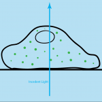
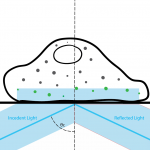
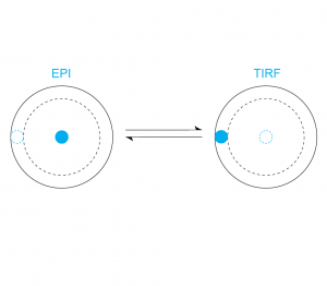
In these images you can see the difference between the two modes of illumination. In these images the green particles are the excited fluorescent particles and the grey ones are the unexcited fluorescent particles. From these images it also becomes clear why for a thinner region of interest TIRF-microscopy is preffered. But this is very dependent on the type of sample. Thus the goal designing this micrscope which will combine these two modes of illumination into a single microscope and allowing to switch between these modes easily.
Lightpath
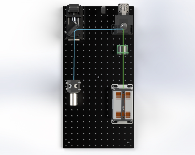
The first step in designing any type of optical system is figuring out the optical components needed. This needs to be done with the goal of combining the two modes of illumination. In order to switch between EPI and TIRF illumination the incident light should switch between regular incedence and the critical angle. This can be done using several methods. The method most applicable to our goal however is translating the light source at the entrance pupil of the objective. As depicted in the image below, by shifting the illumination path into the critical region, the incedent light will be at the critical angle.
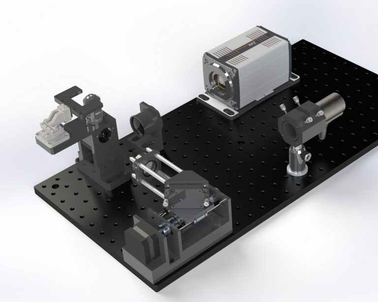
Microscope
Software
There are two software controls for this microscope. The linear stage is being controlled via an arduino board, which drives the steppermotor. Also the stage is being controlled via an self-written software package.
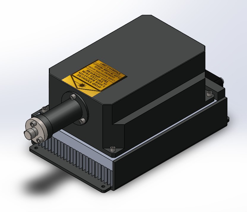
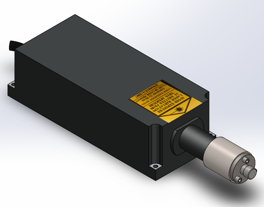
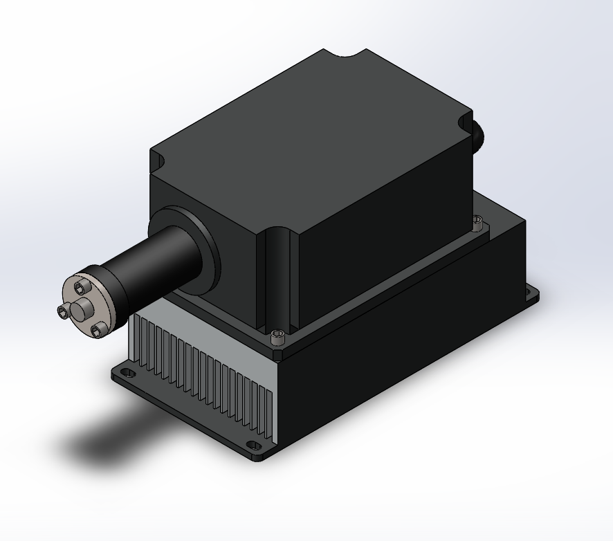
The laserbox is a contained unit of 54x34x23 centimeters and contains everything in order to select between multiple different wavelengths. All this box requires is a single power plug input and it has a single multimode fiber output on which all the different wavelength lasers are being outputed. The wavelengths that are availble in this laserbox are of the 405, 473, 532 and 640 nm wavelengths. These lasers can be used to activate different types of fluors. Varying from fluorescent dyes like Alexa and Cy5 for example all the way to DNA stains like DAPI and SYTO 9.
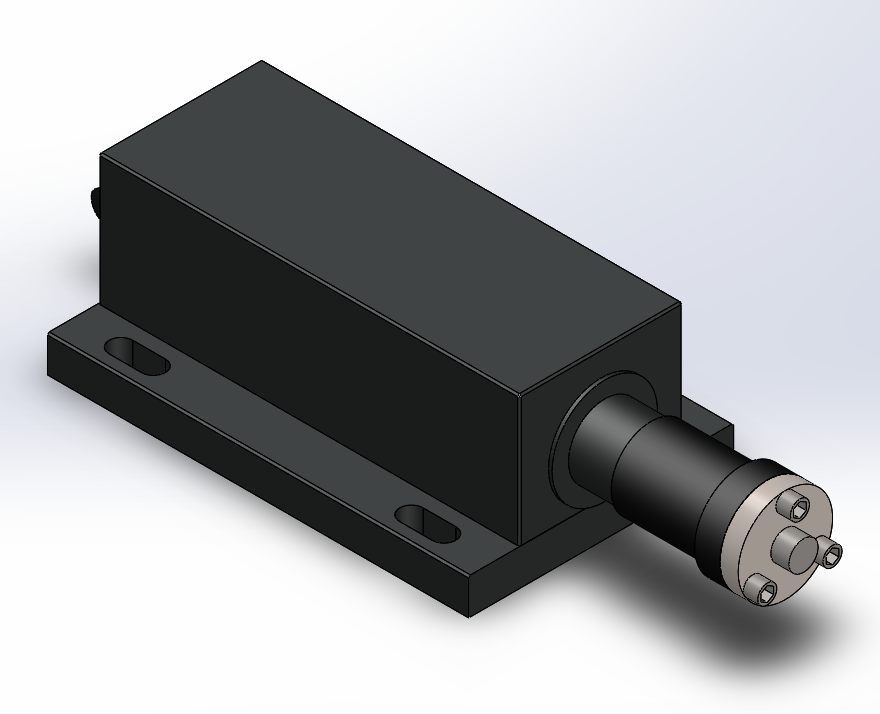
The lasers
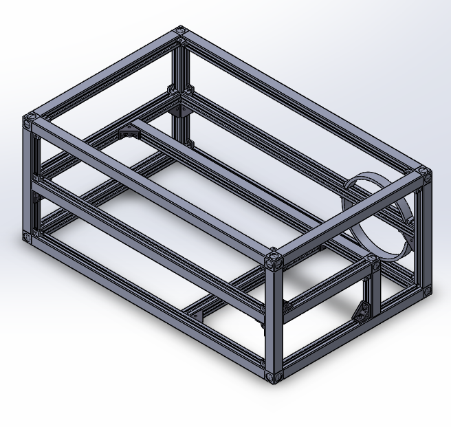
The construction
The skeleton of the laserbox is constructed using Bosch profiles. This has been designed in this way because it greatly reduced the complexity and therefore the ease in assembly of the final box. Using some 3D printed mounts the panels can be mounted in this frame. And on the panels the lasers and the laser control units can be mounted. With just a few screws for each part and the simple design approach this laserbox can be manufactured and assembled by anyone with a screwdriver and the parts.