Highlights DEMO
DEMO has become increasingly important for research in recent years.
Obtaining grants, working on international projects, collaborating in revolutionary medical innovations, increasing safety, and research into sustainability. DEMO has contributed to successes in all these areas.
Just as the size of a project may vary, DEMO's contribution may be big or small; some projects may require a one-off contribution, some may continue for many years and sometimes there may be a request for a follow up to a project that was rounded off years earlier, etc. There is an enormous diversity in every respect.
But DEMO is proud of all its achievements! Achievements that have led to DEMO having a very good reputation and being able to boast a considerable number of highlights.
Flameless Combustion
The set-up is an installation to study flameless combustion (FC) by creating relevant conditions for this in a controlled manner and using optical diagnostics to carry out measurements.
DEMO has built this set-up from a flow chart and, needless to say, in consultation with the client. There had to be enough space for the optical measuring instruments, whereas the set-up had to remain as compact as possible.
Electronics engineers at DEMO also work on this project and there are regular discussions with the client to get input for the flow charts.
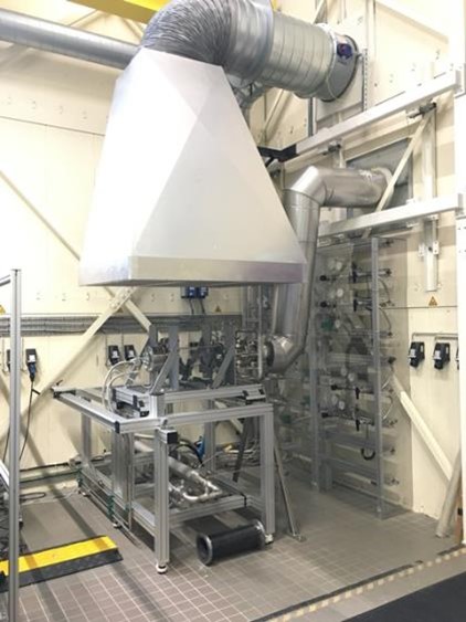
For FC, oxidizer must be diluted (a low O2 content is created by adding inert gases such as nitrogen and CO2) and reactants must be preheated above the auto-ignition temperature. This results in a combustion regime with low-peak temperatures and broken reaction zones, resulting in low NOx emissions. The long-term goal of this lab is to develop FC for gas turbine applications.
In the current combustion chamber design, high-speed beams enter the chamber in a location radially relative to the central axis, leading to internal recirculation zones.
This allows hot burnt product gases to be recirculated towards the entrance, so that fresh gases can be both diluted and preheated. In the burner head, the fuel and air jet are coaxially arranged, resulting in a partially premixed mixture at the outlet of the jet in the chamber. The exhaust gases are cooled by the addition of air before being discharged through an exhaust gas pipe.
Optical access is obtained by using a quartz tube as a combustion chamber or a steel chamber with quartz windows (when the pressure is higher).
Shiver
In early 2020, DEMO received an application for a project. More than a year later, we reached the manufacturing phase of the “SHIVER” project.
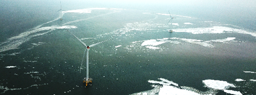
SHIVER is the name of the consortium project by Delft University of Technology, Aalto University and Siemens Gamesa Renewable Energy, with funding by TKI Offshore wind energy. The goal is to develop an advanced calculation model that can be used in the design and optimisation of offshore wind turbines. The calculation model is designed to calculate vibrations to the structure caused by floating ice. These vibrations are a major threat to wind turbines in icy waters. Renewable energy at sea is the EU strategy for the coming decades to make European economies sustainable. For this purpose, the plan is to construct large offshore wind farms, which include the northern waters. Floating ice is then an important dynamic load criterion for the service life of these wind turbine structures.
To develop the calculation model, a simulation model is needed to quantify the ice loads on these mast structures. The behaviour of ice is non-linear, resulting in a non-linear interaction between ice and structure. The field of research is the resonance of the mast at the moment that the ice load falls away (breaking ice). There are still many unanswered questions in ice mechanics that are related to this. What exactly happens in the ice-structure interface during the interaction process is unknown. Extensive research is needed for this.
Scale-model experiments take place in the Aalto Ice Tank in Otaniemi, Finland.
Aalto University has a unique facility in the form of a square test basin, where an ice layer can be generated to carry out these kinds of experiments.
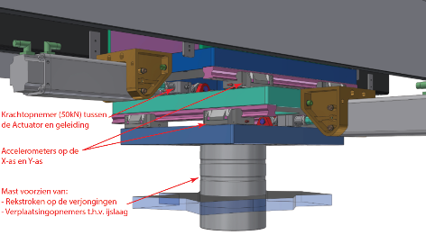
The CEG offshore engineering department and DEMO have jointly engineered a simulation model, in which a scale model of the turbine mast can be subjected to imposed displacements, frequencies (up to 15 Hz) and prescribed forces. This allows the mast to be tested for deflection and fatigue. This has resulted in an X-Y table powered by two 16 kN actuators. Sensors are placed at a number of locations in the structure to monitor the ice load on the structure (see illustration).
The entire structure is placed under a travel beam trolley.
For additional background information on the above article, please refer to the links below:
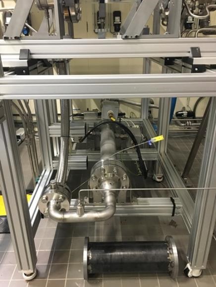
Ultrasonic X-Y welding table
In 2017, DEMO built an Ultrasonic X-Y welding table for Aerospace Engineering. AE uses this to study the continuous welding of thermoplastic composites. In subsequent years, we have added some upgrades to the set-up.
The industrial sector has used stationary ultrasonic welding for some time now. This process permanently connects two composites by vibrating a sonotrode (stainless steel press with a surface of ~2x3 cm) ultrasonically, while pressing it on the workpiece with a few hundred kg of force. This results in a temperature of several hundred degrees Celsius and melts the materials together in a very short time.
The innovative part of this study is that the workpiece can be moved under the sonotrode, creating a line weld, which enables new geometries.
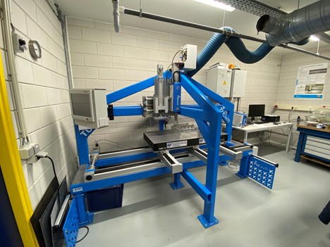
The challenge was to build a table configuration that can move a metre over the X-axis with a precisely controlled speed and which does not deflect by more than 0.05 mm under a load of up to 4 kN. To achieve this, the choice was made for heavy linear guides by Festo including an electrical actuator, onto which an optical table by Thorlabs was placed. To support this assembly properly and to accommodate the ultrasonic welding machine, a reasonably heavy-duty steel frame has been built. The assembly can be seen in the photograph below.
Afterwards, there was a preference to add an extra press to the system, which, even after the welding, could provide the workpiece with pressure for a while, so that it can cool down without deforming too much. To achieve this, a ‘Servo Press’ by Festo was added to the set-up.
The researchers also wanted to be able to accurately measure the temperature of the workpiece during welding, for which additional sensors were integrated into the existing system.
The whole set-up consists of various electrical systems from different suppliers. DEMO has developed the electronics and software to bring all this together into a working system, where researchers can enter their variables directly and the welding process and horizontal movement can be controlled and read out synchronously.
This is a good example of close cooperation between our mechanical and electrical departments which has resulted in a unique solution, as well as the possibility to extend the system afterwards, if the customer has developed additional requirements during the study.
HPTC
HollandPTC has been located behind the RID at the campus since 2018. HollandPTC is one of three proton therapy centres in the Netherlands. Proton therapy is a relatively new form of radiotherapy in the treatment of cancer, in which the tumour can be irradiated precisely with a proton beam. The major advantage of this treatment is that it can be determined relatively accurately where the energy of the protons is released in the body. In purely medical terms, it means that less surrounding tissue is damaged, thus reducing the risk of complications and side effects of radiation. This is particularly useful in areas such as the prostate gland, the eyes, brain and neck area.
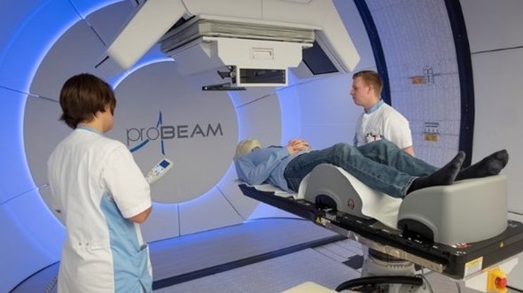
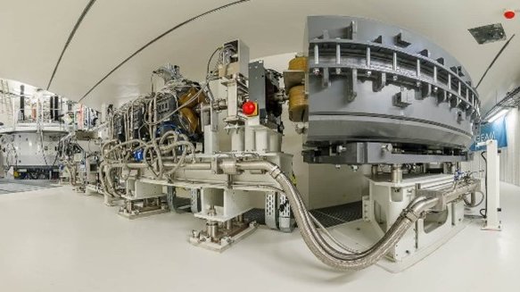
The protons are generated in a cyclotron, actually using the same principle as for CERN, and then ‘clouds’ of protons are radiated towards the patient through the gantry that can move 360° around the body.
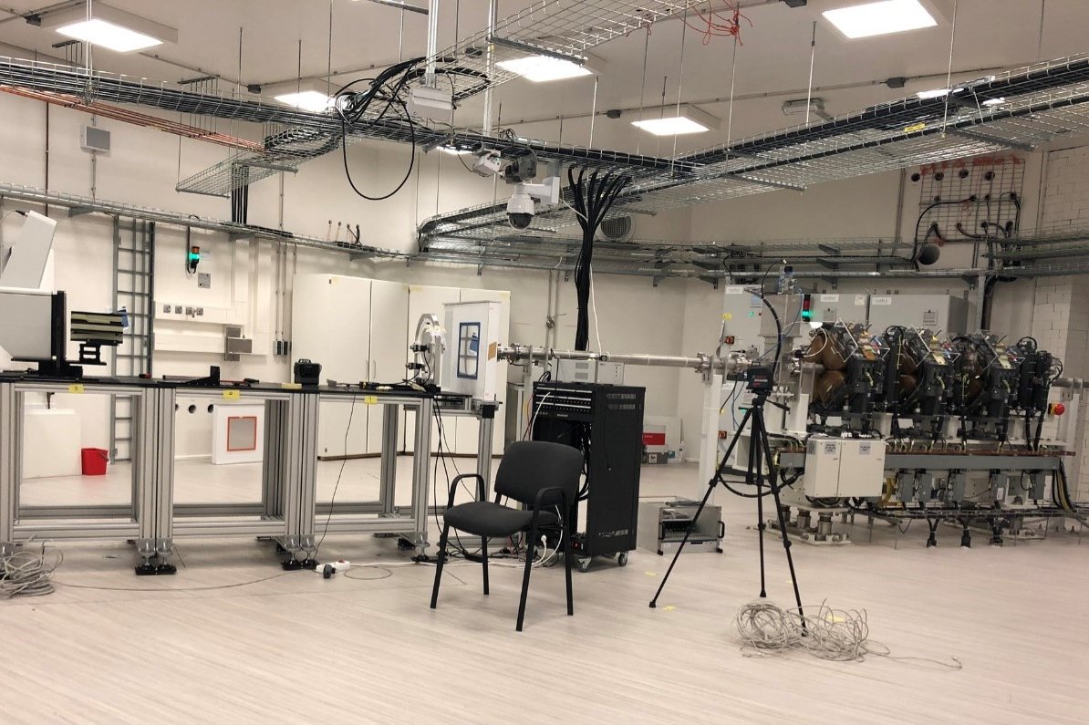
HollandPTC has three treatment pathways, two regular gantries and an eye treatment pathway, which is the only one in the Netherlands. Aside from these three medical beams, there is a beam for R&D work. Here, research will be conducted into new irradiation techniques and determining their effectiveness. But also more basic research on how DNA recovers when it has been damaged, and totally different fields like the irradiation of components for use in space.
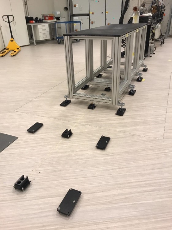
DEMO is involved in the layout of the research bunker. We have delivered a modular table system that is aligned within 0.1 mm in all directions in respect of the proton beam. The experiments can be built on these tables. As the tables have kinetic supports, the tables can mutually be exchanged or driven out of the bunker to build up the experiment elsewhere and then putting it pre-aligned for the beam. We have also been involved in making cabling between the controller chamber and the bunker itself, and the layout of the biological laboratory.
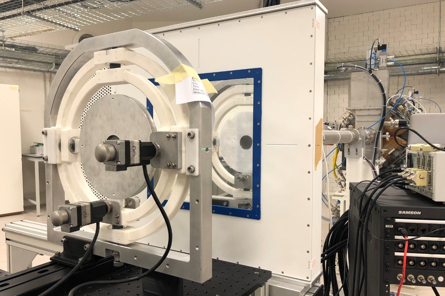
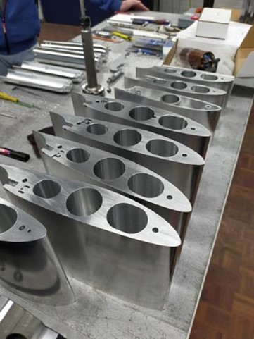
The first instrument, a double ring set-up, basically allows the beam with a diameter of a few mm to be increased to a maximum of 240x240 mm. This makes it possible not only to irradiate very large samples in one go, but also mice, for example.
The double ring consists of a couple of components, in which the beam is converged or collimated each time. The beam first goes through a lead foil. Then the intensity is examined with a detector that is in the beam. This is followed by the actual double ring which is made up of a lead core with an aluminium shell. Then another filter can be placed to change the wavelength of the protons to be collimated just before the detector.
The crux of the set-up is in the lead ring with aluminium shell. It must be very accurately aligned in five axes to obtain a nice homogeneous beam. The difficulty here is that the beam is invisible.
Initially, we had made a very simple, non-adjustable holder for the double ring, but this did not work adequately. It soon became clear that you actually want to be able to move all the axes independently of each other, in order to make minor adjustments. With that in mind, we created a kind of gyroscope which is motor powered, so you do not have to enter the bunker for every adjustment. That is a rather time-consuming process, taking into account the safety requirements regarding radiation. The ring actually becomes radioactive during irradiation. The ring is now well aligned and we are working with collimators. At first, loose plates are taped together to see what and how much is needed, and it is then executed neatly.
The ultimate goal is a fixed set-up that can be taken from the cupboard and placed on the table, so that it is immediately in the exact position. With that in mind, the next step is to measure the position of the double ring with the measuring arm very precisely, and then to make a final fixed set-up in the proper orientation.
When all that has been done, there must be another version with different sizes for lead and aluminium, a trolley to be able to transport the mice, to keep them asleep and to align them with the beam. Also, all kinds of stages and flippers to put various samples in the beam, moving eye phantoms, radiation shielding arrangements, various 3D collimators, moving phantoms to mimic breathing, ….
NOVAIR project
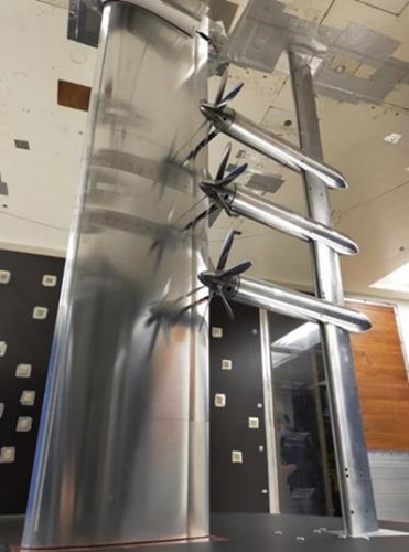
The NOVAIR project studies how hybrid/electric aircraft configurations can be designed more efficiently. The use of several small, electrically powered propellers can increase efficiency, but this leads to interaction effects that must first be studied, before we are able to say anything about the aircraft.
The set-up was created to study the aerodynamic interaction between multiple propellers and a wing with flap. This interaction is important for the efficiency of the system, and is being studied as part of a European research project aimed at hybrid electric aircraft with distributed propulsion.
The model has been tested in the 2.25 m x 3 m low-velocity wind tunnel at DNW in the Noordoostpolder. The tests were carried out at a wind velocity of 108 – 144 km/h, and the propellers were rotated between 6,500 and 11,000 rpm. The model was installed on an external balance to measure the forces on the wing, and the propeller forces were measured with an internal force sensor. The pressure holes have been used to record the effect of the propellers on the pressure distribution on the wing. In addition, a microphone array was used to measure the sound of the system.
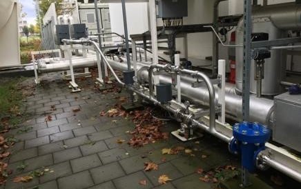
Flood barrier: measuring of glass constructions by Deltares and TU Delft
Rising water levels of both the sea and our rivers are a topical issue. To protect us from flooding, this water-level rise must be compensated by means of dyke elevations. Due to enormous flooding in the river basin of the Meuse, Waal and Rhine 25 years ago, 250,000 people had to be evacuated. In many places in the Meuse area, the Water Board had to set up emergency dykes inland to prevent the flooding of a huge area.
On commission for the contractor consortium Strukton/Van den Herik, Rijkswaterstaat and the Limburg Water Board – in collaboration with TU Delft – Deltares carried out load tests on a new type of flood barrier. The new concept is to use glass.
To prevent flooding, a dyke or quay (vertical barrier) can be raised. However, for normal water levels this also restricts the view of the river. A removable barrier meets this requirement. The Limburg Water Board already has 200 of them, and they cannot handle more. They must all be installable on location within 48 hours, and that will no longer be possible with > 200 structures.
In order to meet the needs of the residents as far as possible, in terms of a permanent open view of the surrounding area, a solution using glass has been chosen.
The new concept comprises laminated glass panels. Having erected a test set-up, in which the glass was tested under extreme conditions (including waves and floating objects that could damage the barrier), it could be assessed whether the glass is suitable for use as a permanent dyke elevation. By using several layers of toughened glass, the panels turn out to be able to absorb major impacts. In case of glass damage, initially only cracks appear in the glass, but the structure remains intact, due to the multiple layers.
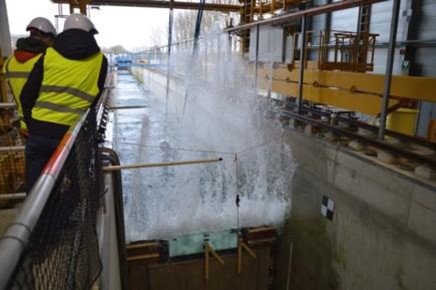
The test set-up was created in the Delta Flume at Deltares. It is a channel (flume) that measures 300 metres in length, is 5 metres wide and 9.5 metres deep, in which a wave generator can produce artificial waves. Its highest significant wave height achievable is no less than 2 metres, with a record height of an individual wave of 4.7 m. To simulate the impact of floating objects, a tree trunk was used in the waves to collide with the glass.
To be able to measure the load capacity of the structure and deformation of the glass itself, laser displacement sensors were used for the structure and strain gauges for the glass itself.
The measurement results show that the selected glass type and thickness are suitable as a flood barrier. Even after artificial breakage, the structure remained intact and the flood barrier proved to be sufficiently safe.
Once again, a great collaboration between Deltares and TU Delft!
Want to know more?
Gyroscope
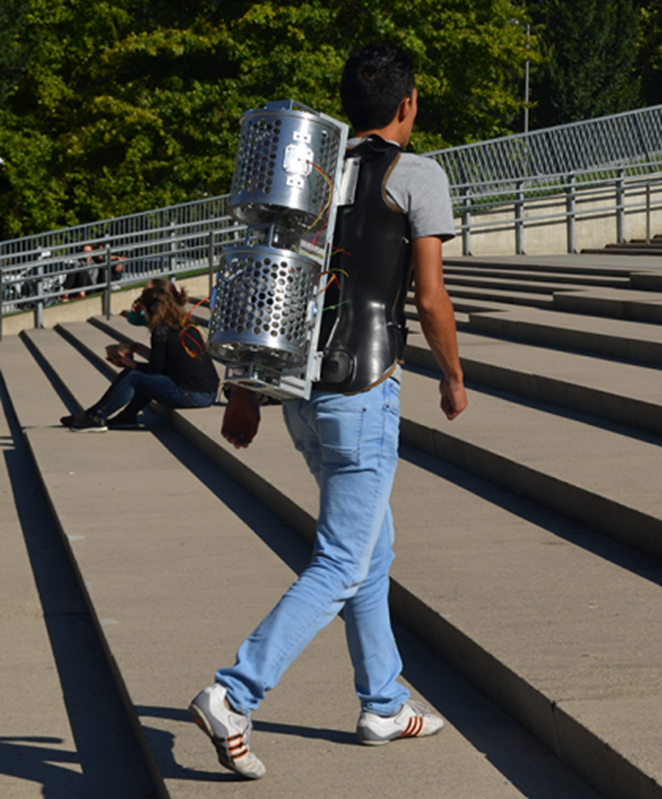
The Faculty of ME is currently conducting research on gyroscopic balance assistance. Falls are a common cause of injury, and the elderly (65+) are particularly at risk.
Wearable robotics offer a solution for this in the form of a ‘backpack’ containing two actuators – Control Moment Gyroscopes. In essence, a gyroscope is a sort of spinning top: a symmetrical mass that can spin on a central axis. As long as the mass is spinning, it will resist a change in the orientation of the axis. When a spinning top is suspended in a cardanic mounting (gimbals) that allows it to move freely, it works as a gyroscope and can be used as an orientation instrument.
Mechanical and electronic insights, among other things, should enable the construction of a lightweight yet effective, wearable device for assisting balance. Initially, DEMO was asked to help with the software for this, but the project grew to become an extensive collaboration.
MRI scanner
State of affairs in 2017
MRI scans could be better and less expensive. That is what Andrew Webb, an MRI Physics professor at Leiden University Medical Center, says. For his research, he recently received the 2017 Simon Stevin Master Award.
The largest technical-scientific research prize is worth half a million euros. Webb wants to use this to develop new MRI techniques to detect diseases such as Huntington's disease and Alzheimer's at a much earlier stage.
In addition, the professor develops inexpensive mobile MRI scanners that can be used in developing countries. For example, hospitals that do not normally have access to this type of medical equipment can still use a scanner that travels from place to place.
The inexpensive mobile MRI has a convenient side effect: it accelerates the process of the more expensive MRI scanners now used in hospitals. This relates to the software that Webb has to develop to control the mobile scanner. The best images are quickly filtered out of the device, which means that this could possibly accelerate the scanning process in the future.
DEMO
This project is a partnership with Leiden and EEMCS. Delft is developing the mathematics required to reconstruct the image.
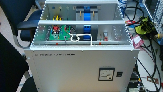
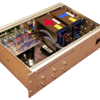
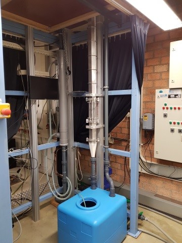
DEMO has designed the permanent magnet ring (see photo) and is also working on the RF power electronics (photo below). The project is still in the early stages of a 4-year research and we will soon be delivering the first parts. Improvements will then be made to the set-up based on the research results.
Update 2019
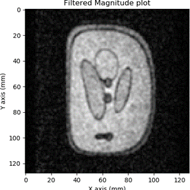
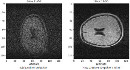
Since 2017, there have been many new developments in the low-cost MRI project. The first 3D images have now been made using the set-up at LUMC. This set-up uses the previously developed RF amplifier and the new gradient amplifier. The first ‘magnet’ has been replaced by a new set of rings developed in Leiden that contain a large number of far smaller permanent magnets that, together, create the static field.
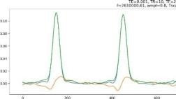
This magnetic field is extremely steady within the volume of the MRI, but for imaging use, it is necessary to introduce a gradient in the x, y and z direction. In tests, the DEMO gradient amplifier was shown to produce less noise than the commercial gradient amplifiers used. This reduces the time required for a scan, and our amplifier is significantly cheaper even including the design costs.
The first magnet has returned to Delft and is now housed at the mathematics lab. A second MRI set-up with the same RF amplifier has now been built there. This set-up is used for research into a mathematical algorithm for making an MRI scan with a non-linear magnetic field. This makes it possible to use a magnetic field that is easier to make, resulting in an even cheaper system. The beauty of this new technique is that it can also be used on existing MRI scanners, to correct small variances in the magnetic field.
A Software Defined Radio (SDR) application has been created for the set-up in Delft. This generates the RF pulses that must be emitted and demodulates the received signal to low-frequency pulses, which consist of a real and imaginary part – exactly what the mathematicians need to create an image. The SDR was created using GNU Radio that generates Python code. Subsequently, an additional Python module was written, which can be used by researchers to carry out measurements.
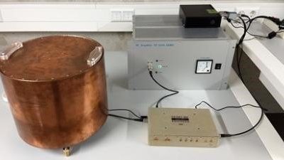
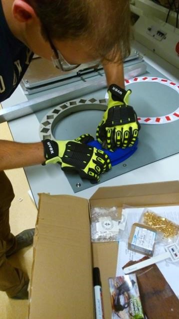
In order to measure the MRI signal, a signal is first emitted from the RF amplifier to a coil (in the copper cylinder). This signal consists of two RF pulses of 300 Vpp and 600 Vpp at 2.6 MHz. A bottle of water placed inside the coil is used as a test sample. The two pulses sent to the bottle cause the water itself to return a pulse shortly afterwards. This signal is received by the same coil and is so weak that it needs to be amplified more than 30,000x in order to use it. Suddenly we had a eureka moment. IT WORKS!!!!
Update 2020
At the end of September, a huge step was taken in Leiden with the gradient amplifier for the MRI set-up. With an added filter, it now creates so little noise that its noise contribution in a scan is negligible. This was also true for DEMO’s RF power amplifier. This means that we are very close to the theoretical minimum noise. This is very important, because the signal strength in a Low Field MRI is very weak. Less noise means that a scan proceeds faster or that a higher resolution can be achieved in the same time frame.
The resolution required to scan hydrocephalus, for which it was designed, had already been achieved earlier.
Together with special coils wrapped onto a cylinder, the gradient amplifier allows a magnetic field to be created in the x, y, and z direction. This allows a point to be scanned in the patient to be determined in three dimensions. The set of points (“voxels”) realises the MRI scan.
Nice to know: in Berlin and at Penn State University (USA) the RF Power Amplifier is already being replicated to create a similar set-up there. The design has been released via open source so that inexpensive MRI scanners can be made worldwide.
SESAME
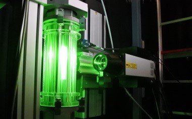
SESAME is an international project working on the safety of a nuclear reactor with solid radioactive rods. DEMO's set-up for this, also known as SEEDS (Seven rods bundle Experiments in Delft for Sesame), consists of seven stainless steel rods that mimic the reactor rods. In this research, the flow of water passing the stainless steel rods is examined using a laser. The purpose of this is to map the different types of water flow surrounding the stainless steel rods: laminar or turbulent for various flow rates. This information can then be used to attain the highest possible heat exchange between the water and reactor rods. At DEMO, the challenge was to achieve differing preferred configurations, a length of a two-metre long set-up, and a transparent viewing window for the laser in the set-up.
Fizzy robot ball
“Fizzy is a robot ball that challenges young children in hospital to move and play. In this way, Fizzy contributes to faster convalescence, it promotes the child’s development and makes the time spent in hospital more pleasant.” The robot ball can vibrate and can roll towards or away from the children.
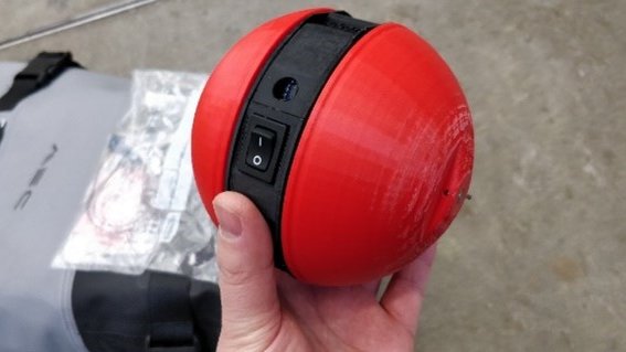
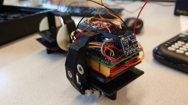
The Fizzy robot ball has been redesigned to make it more robust (so that children can kick the ball). It has been fitted with a stronger propulsion so that it can roll away faster and the larger battery ensures longer playing time. The robot ball has been equipped with a new frame that contains the electronics and propulsion, two scale components that can rotate and a rubber shell for a soft touch.
The Fizzy’s initial design contained many cable connections, which made the electronics fragile. To solve this issue, a PCB has been developed with modules that power the two motors. Additional features, such as a bluetooth connection and speaker have also been added. The PCB has made the electronics in the Fizzy more robust. In the design, the size of the PCB in the Fizzy has been taken into account using a 3D model.