DeLight
The SuperCritical Water Reactor, or SCWR, is one of the Generation IV nuclear reactor designs. This innovative reactor design uses water in a supercritical state to cool the fuel rods and then drive the turbines, to produce electricity. By raising the temperature and pressure of the coolant, a higher thermal efficiency of about 44% can be obtained. This is a significant increase compared to current reactors which operate around 33%. In 2009 the basic design of the High Performance Light Water Reactor (HPLWR) was presented in literature. This design is unique in that it has a three pass core with intermediate mixing plena to reduce peak cladding temperatures. It is the result of a European Framework program in which many different institutes all across collaborated. At the section 'Physics of Nuclear Reactors' (PNR) a novel design idea was launched for the HPLWR: to use natural circulation. As the supercritical water heats up when flowing through the reactor, the density decreases significantly, and this change in density could be used as a driving force to make the coolant circulate. This adds a layer of inherent safety to the design, as it removes the need of large feedwater pumps. This type of circulation already exists for boiling water nuclear reactors, e.g. in the ESBWR (GE website). Because these natural circulation flows can become instable with the occurence of 'density wave oscillations', it is imporant to study their stability at various conditions. This has been done extensively at PNR over the past decades for the ESBWR, both through experiments (DESIRE and GENESIS facilities) and through simulations.
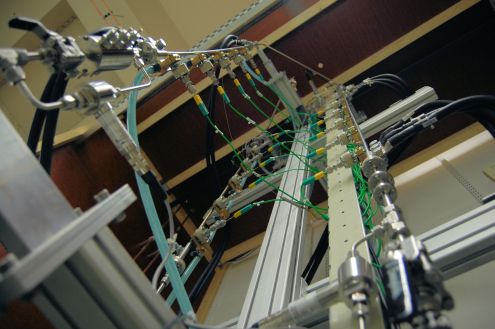
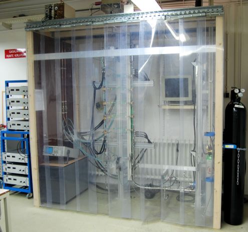
Based on a set of derived scaling rules (see Rohde et al., 2011) an experimental facility was developed which mimics a natural circulation HPLWR. This facility was named DeLight ('Delft Light water reactor facility'), and will be introduced in more detail on this page. The goal of this setup is to study the stability of this natural circulation supercritical reactor. The funding was provided by the NWO VENI scheme (project number 680-47-119). A schematic drawing is shown in Fig. 1 and some of the dimensions are listed in Table I. For all the dimensions, please consult this drawing (click to enlarge). On this page some photos are shown of the setup as built. The loop is constructed using stainless steel tubing (6mm ID for the core sections, 8 mm ID for the riser and downcomer). The total height of the loop is close to 10 m. Up to 18 kW of heating (twice the scaled power requirement) can be added in 4 different heating sections (3 cores and the moderator channel which mimics the water rod presence). Heating is done electrically (providing a uniform heat flux boundary) by sending a current through the core tubes (up to 600A per core element using Delta SM15-200 power units). The power rating of each core can be controlled individually. Each core is electrically insulated from the rest of the setup using a Teflon ring mounted in between 2 flanges. Valves are mounted between the core sections, at the inlet and exit of the core and at the exit of the riser. These can be used to introduce local friction values in the system, such as inlet systems or the plena mimicking actual reactor designs. It is well known that these local friction values can have a significant effect on the stability of a system. To provide a stable pressure level, a buffer vessel is present at the top of the loop which has a moveable piston (Parker Series 5000 Piston Accumulator) connected to a nitrogen gas cylinder. By positioning this piston higher or lower the pressure level in the loop can be set at 5.7 MPa. Two heat exchangers (HX in Fig. 1) are mounted in series at the top section of the loop to extract the heating power and to set the inlet conditions. The first one uses cooling water and cools R23 to 20°C. The second is an evaporator with R507a in which R23 is cooled down to a minimum temperature of -25°C. Due to the differential thermal expansion of the core sections (wall temperatures can reach over 200 °C) and the other parts of the loop, the tubes are connected to the wall using moveable spacers which contain 2 prestressed springs. The bottom connection between the different core sections is done through a flexible tube of woven steel.
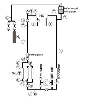
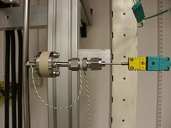
The loop contains a large number of sensors to closely monitor the thermo hydraulics. At the top and bottom absolute pressure drop sensors are presents (p symbol in Fig. 1, ± 0.15%). Each valve is combined with a differential pressure drop sensor (Δp symbol in Fig. 2, ±200/500 mbar) to measure the local pressure drop. The different core sections each contain 5 type K thermocouples to measure the local fluid temperature as it passes through the core (T symbol in Fig. 1, ± 0.1K). These thermocouples also have to be insulated electrically from the core to prevent the feed current passing through them. This was also done using Teflon rings, as shown in Fig. 2. The individual thermocouple channels were calibrated carefully using 3 reference thermocouples which were calibrated over the entire temperature range by a certified body. As shown in Fig. 2 additional thermocouples are placed in the riser and down comer section, as well as on the secondary side of the heat exchangers to monitor the heat removal. The R23 mass flow rate is measured using a coriolis meter (F symbol in Fig.1, ± 0.25%, including a density measurement: ±0.005 kg/m³). Apart from the core sections the entire setup is insulated using Armacell©
HPLWR | DeLight | |
Core average mass flux (kg/m^2s) | 1665 | 1232 |
Power fuel per pin (kW) | 114 | 9 |
Hydraulic diameter (m) | 0.00562 | 0.006 |
Core Length (m) | 4.2 | 0.8 |
Table I: Comparison of the dimensions and operational parameters of the HPLWR and DeLight
International peer reviewed journal publications:
- T’Joen, C., Rohde, M., Experimental study of a coupled thermo-hydraulic – neutronic stability of a natural circulation HPLWR, Nuclear Engineering and Design, (accepted for publication)
- Rohde, M., Marcel, C.P., T’Joen C., Class, A., Van der Hagen, T.H.J.J., Downscaling a supercritical water loop for experimental studies on system stability, International Journal of Heat and Mass Transfer 54 (2011), pp. 65-74.
- Marcel, C.P., Rohde, M., Masson, V.P., Van der Hagen, T.H.J.J., Fluid-to-fluid modeling of supercritical water loops for stability analysis, International Journal of Heat and Mass Transfer 52 (2009), 5046-5054
International conferences:
- T’JOEN, C, ROHDE, M., Experimental study on the stability of a natural circulation driven super-critical water cooled reactor, 22nd International Symposium on Transport Phenomena, 8-11 November 2011, Delft, The Netherlands
- T’JOEN, C., KAM, F., ROHDE, M., Stability research on a natural circulation driven SCWR, Proceedings of the NURETH 14 Conference, 25-29 September 2011, Toronto, Canada
- T’JOEN, C; ROHDE, M; Experimental study on natural circulation driven HPLWR, Proceedings of the ISSCWR 5 Conference, 13-16 March 2011, Vancouver, Canada
- T’JOEN, C; ROHDE, M; VISSER, DC; LYCKLAMA A NIJEHOLT, JA; ROELOFS, F; VAN DER HAGEN, THJJ; Preliminary natural circulation data of a scaled HPLWR experiment, IEAE Technical meeting on heat transfer, thermal-hydraulics and system design for supercritical pressure water cooled reactors, 5-8 July 2010, Pisa, Italy
An overview of our experimental data of DeLight is given here. For access to the experimental data contact dr.ir. Martin Rohde.
Dimensions and more photo's are here.