Dredging Engineering
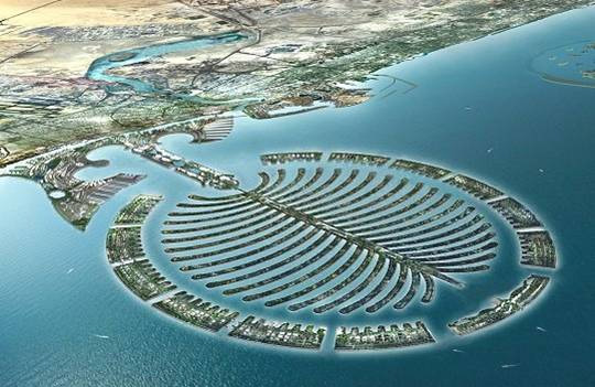
Large volumes of sediment are displaced nowadays using different types of dredging equipment. Especially the last decade, large land reclamation projects attained global attention. Examples of these enormous projects are the new airports in Hong Kong and Singapore, the large land reclamations for ports and industry in Singapore and very recent the spectacular projects in Dubai like the palm Islands and “the World”. All Dredging processes involve slurry flows and are dominated by erosion, transport and sedimentation under special hydraulic conditions.

These large volumes of sediment can only be displaced economically by properly designed equipment. To design dredging equipment, one first has to understand the processes involved.
The dredging process can be divided into the following Phases:
- Excavation
- Vertical Transport
- Horizontal Transport
- Deposition / sedimentation
The boundary conditions for the design process must follow from numerical models developed for these dredging processes. A continuous improvement or developing new models is however important because the recent developments like the increased scale, larger waterdepth and more sustainable development (energy consumption and environmental regulations). These models are often based on experimental research. For this purpose the section has a laboratory available with a slurry circuit (see facilities). Apart from in our own laboratory research is carried out as well in facilities of the industry since all research programs are carried out in close cooperation with the dredging industry.


Apart from the above mentioned unique fundamental research more applied research is carried out for special dredging equipment or dredging applications. For instance design of excavating equipment working in very deep water (2000 m).
Management assistant of the Section Offshore and Dredging Engineering
Pauline de Ruijt-Franke
- +31(0)15-2782889
- A.C.M.deRuijt-Franke@tudelft.nl
-
34.B-3-250
Present: Monday morning, Tuesday and Wednesday
Publications
-
The hydraulic circuit consists of a pump pipeline system. The pump is driven diesel direct with 160 kW on the axis of the pump. The impeller diameter can vary from 400 mm to 600 mm. The impeller revolutions can vary from 375 rpm to 1500 rpm with speed control. The pipeline has an internal diameter of 150 mm and a total length of about 60 m. In the pipeline a vertical U-loop, with a length of 2*10 m, is mounted for density measurements. Also an inclined U-loop, with a length of 2*12 m, is mounted for resistance measurements in inclined pipelines. The inclination angle can vary from 0 to 90 degrees. The pump is capable of generating a line speed of up to 8 m/s with a head of about 500 kPa. In the system a mixture forming unit is mounted to control the concentration of sand particles in the water. Different grain sizes can be used for the experiments.
-
In 1922 the Chair of Dredging Equipment was established by Prof.ir. C.M. van Wijngaarden The Chair was mainly involved in the design and production of dredging equipment based on extrapolation of existing equipment.
In 1962 Prof.ir. W.A. Bos was appointed. Because of the problems at the Dutch Delta Works research into the dredging processes became important, resulting in building a dredging laboratory in the period 1968-1972.
Prof.ir. J. de Koning was appointed in 1977. The Chair now focused on the design of dredging systems based on the dredging processes. This required more fundamental research, resulting in the first PhD projects in the early 80’s.
In 1993 Prof.ir. W.J. Vlasblom was appointed. The research developed from stationary processes to non-stationary processes, the design from an equipment approach to a systems approach and the system dynamics and control engineering became more and more important.
Since 2007 Prof. dr. ir. C. van Rhee is the chair of the research group.
-
The Excavation can be mechanically or hydraulically. In both cases sediment is transformed from a solid into a fluid state in a very short time.
The phase change can be regarded as dynamic soil mechanics or high concentrated slurry flow. Soil mechanical parameters as friction angles and permeability as well as fluid mechanical properties as viscosity, and settling velocities play an important role. Deformation rate is very large during excavation. Combined with dilatant behavior this leads to large negative pore pressure or even cavitation of pore water.Although Vertical Transport can be performed mechanically (for instance with a grab dredge), in most cases a hydraulic mechanism is used using (submerged) centrifugal pumps. The largest part of the sediment dredged is used as building material and is therefore not fine grained. The flow regime typically encountered is therefore heterogeneous. The suction pipes are mostly inclined. Production limiting factors are available pumping power and minimum pressure at the suction inlet of the pump.
For relative short distance sediment is transported by hydrotransport in most cases. With increasing distance (in dredging practice typically from 10 – 100 km) trailing suction hopper dredges (TSHD) are often employed. In that case the sediment is transported in the hopper (cargo hold) of the dredge. A TSHD is a vessel equipped with one or two suction pipes. At the locating where the sediment is extracted the suction pipes are lowered to the seabed. At the lower end of the suction pipe a special designed suction mouth, the so-called draghead is loosening the sediment with the help of water jets and / or teeth. The erosion of sand using high velocity water jets is a very complicated physical process where soil mechanical and rheological properties play an important role.
The sediment-water mixture is transported through the suction pipe and discharge in the hopper. Here the sediment settles and the excess water flows over board. The sedimentation process encountered is very typical. The sediment settles from an overloaded density current in a confined space. Flow velocities are below the deposition limit but still high enough to have an influence on the sedimentation velocity. In most cases a certain part of the incoming sediment will not settle and will flow overboard. This so-called overflow loss is dominated by the particle size distribution, slurry concentration and slurry discharge by unit hopper area.
Deposition of dredged material can be done under water or above water. In both cases hydraulic processes are dominant. Under water density currents develop from which sediment settles and under water bodies are developing. Density and stability of these sand fills are depending on method placed, particle size distribution and operational conditions. Above water sand bodies are forming from highly concentrated flows. Densities and slope angles of the bodies are depending on specific discharge and grain size.
Thorough knowledge of the processes taking place during the above described stages is very important to design dredging equipment (equipment building industry) and to estimate and design dredging projects (dredging contractors & consultancy and engineering companies).